![]()
![]()
![]()
![]()
![]()
![]()
![]()
![]()
![]()
NX Nastran V10.0 -- Novedades (Diciembre 2014)
Es un placer dar a conocer la nueva versión del “solver” de Análisis
por Elementos Finitos NX Nastran V10.0 -disponible desde el pasado 18 de Diciembre de 2014- el cual llega a
nuestras manos con importantes novedades y notables mejoras en prestaciones,
velocidad de cálculo, mejoras en elementos, nuevas disciplinas de análisis, así
como una larga lista de corrección de errores.
-disponible desde el pasado 18 de Diciembre de 2014- el cual llega a
nuestras manos con importantes novedades y notables mejoras en prestaciones,
velocidad de cálculo, mejoras en elementos, nuevas disciplinas de análisis, así
como una larga lista de corrección de errores.

NX Nastran V10.0 vendrá incluido por defecto en el DVD con
la nueva versión de #FEMAP V11.2,
que estará disponible en el mercado mundial a lo largo del mes de Marzo de
2015.

A complete list of enhancements and corrections can be found in the NX Nastran V10.0 Release Guide.
Dynamics …
1.- Ply Stress and Strain Output for Laminates.
In earlier versions of NX Nastran, output of ply-layer stresses and strains is supported in transient response analysis only when the laminates are modeled with shell elements. Beginning with NX Nastran 10, output of ply-layer stresses and strains is supported in frequency response (SOL 108 and SOL 111), random response (SOL 108 and SOL 111), and transient response (SOL 109 and SOL 112) analyses for laminates modeled with solid or shell elements.
Complex stresses and strains are not computed for QUADR and TRIAR elements that are used to model laminates when SYSTEM(370)=1.
For frequency response analysis (SOL 108 and SOL 111), failure indices and strength ratios are now also computed and output. Because frequency response analysis results are complex, the software calculates the failure indices and strength ratios at discrete phase angles over a full 360 degree range. The worst case value is output. By default, the calculation is performed at every one degree increment. However, you can optionally specify that the software use a different angular increment by specifying the new SWPANGLE parameter. This will affect the output of PSDF, ATOC, CRMS, and RMS results.
2.- Von Mises Stress/Strain results in Frequency Response
Beginning with NX Nastran 10, von Mises stress and strain are computed by default for a deterministic frequency response analysis in SOL 108 or SOL 111 when stress and strain results are requested. The von Mises stress and strain is calculated using the Charron method (For information on this method, see Charron, Donato, and Fontaine, Exact Calculation of Minimum Margin of Safety for Frequency Response Analysis Stress Results Using Yielding or Failure Theories, MSC 1993 World Users’ Conference Proceedings).
3.- Modal and Panel Contribution results for Post-processing
Modal and panel contribution results are needed for post-processors to support analyses like acoustics. Beginning with NX Nastran 10, the output data blocks that contain modal and panel contribution results can be written to the .op2 file for PARAM,POST,-1 and PARAM,POST,-2.
To write the OUGMC, OEFMC, OESMC, OSTRMC, and OQGMC modal contribution output data blocks to the .op2 file, include a MODCON case control command in your input file. Depending on the describers you specify, all or some of the modal contribution output data blocks are written to the .op2 file. Previously, output was limited to printed .f06 results.

Multibody Dynamics …
1.- Modal Damping.
In versions prior to NX Nastran 10, off-diagonal terms were omitted from the modal damping matrices that the software writes to some interface files. These interface files include:
- Standard and state-space MATLAB files.
- Standard and state-space OP4 files.
The NONCUP parameter is used to specify whether off-diagonal terms are omitted from the modal damping matrices written to ADAMS MNF files.
NOTA: RecurDyn RFI files and SIMPACK FBI files do not support damping matrices.
For proportionally damped systems, the modal damping matrix is always diagonal. Thus, the modal damping matrices that the software writes to interface files are perfectly representative.
For non-proportionally damped systems, the modal damping matrix is not typically diagonal. Thus, the off-diagonal terms are omitted from the modal damping matrices that the software writes to standard and state-space MATLAB and OP4 files. This can lead to inaccuracies in the analysis results.
Beginning with NX Nastran 10, the software writes the full modal damping matrix to standard and state-space MATLAB files, standard and state-space OP4 files, and ADAMS MNF files by default. To optionally disable this capability and have NX Nastran 10 write only the diagonal terms of the modal damping matrix to these interface files, do one of the following:
- Include the NONCUP = -2 describer with the ADAMSMNF or MBDEXPORT case control command specification.
- Include PARAM,NONCUP,-2 in the bulk data section of the input file.
If you specify both the NONCUP describer and the NONCUP parameter, the NONCUP describer specification takes precedence.
Rotor Dynamics …
1.- Complex Modal Reduction Enhancement.
You can now specify the reference rotor speed that the software uses to compute the reduced modal basis for a SOL 107 rotor dynamic solve with complex modal reduction.
To specify the reference rotor speed, use the new ROTCMRF parameter. The units for the reference rotor speed specified with the ROTCMRF parameter are the same as those specified in the RUNIT field of the ROTORD bulk entry. If you do not specify a value for the ROTCMRF parameter, the software automatically calculates the reduced modal basis for a reference rotor speed of zero.
Because the solves at other reference rotor speeds are computed from the reduced modal basis, expect the most accurate rotor dynamic analysis results to be at reference rotor speeds close to the reference rotor speed specified with the ROTCMRF parameter.
If rotor superelement reduction is requested with ROTSE bulk entries, unsymmetric a-set reduction is performed at the reference rotor speed specified with the ROTCMRF parameter.

2.- New Stiffness and Damping terms for CBEAR elements.
Currently, you can define the translational stiffness and viscous damping for CBEAR in the plane normal to the rotor axis. Beginning with NX Nastran 10, you can also:
- Define the translational stiffness and viscous damping in the axial direction of the rotor.
- Define the coupling terms for translational stiffness and viscous damping between the axial direction of the rotor and axes in the plane normal to the axial direction of the rotor.
- Define the rotational stiffness and viscous damping about axes in the plane normal to the axial direction of the rotor.
- Define the coupling term for rotational stiffness and viscous damping between the axes in the plane normal to the axial direction of the rotor.
To specify the added stiffness and viscous damping terms for a CBEAR element, enter values in the appropriate fields of the new “TYPEZ” and “TYPER” continuation lines for the PBEAR bulk entry.
3.- Expanded support for CBEAR element properties.
With NX Nastran 9, you could model CBEAR element stiffness and viscous damping as functions of speed and displacement, or speed and force. However, this capability was available only for a SOL 101 rotor dynamic analysis. Beginning with NX Nastran 10, this capability is expanded to include the following solutions for rotor dynamic analyses:
- SOL 108 direct frequency response.
- SOL 109 direct transient response.
- SOL 111 modal frequency response.
- SOL 112 modal transient response.
4.- Composite Relative Displacements and Forces for CBEAR elements
Beginning with NX Nastran 10, you can specify that the software use composite relative displacements or composite relative forces when it looks up speed and displacement-dependent, or speed and force-dependent bearing stiffness and bearing viscous damping. Composite relative displacements are linear combinations of radial and axial relative displacements.
5.- Coupled Solutions in Rotor Dynamics
In prior versions of NX Nastran, time-dependent coupling terms between the rotating and supporting structures are not included in the equation of motion. Because time-dependent coupling terms arise for unsymmetric rotors or supports, the rotor dynamics capability is applicable to structures that have symmetric rotors and supports that are analyzed in either the fixed or rotating reference system, as well as the following two special cases.
- Structures that have unsymmetric rotors and symmetric supports that are analyzed in the rotating reference system.
- Structures that have symmetric rotors and unsymmetric supports that are analyzed in the fixed reference system.
With NX Nastran 10, you can optionally include the time-dependent coupling terms in the equation of motion for SOL 107, 108, and 109 rotor dynamic analyses that are performed in the rotational reference frame. This enables you to perform rotor dynamic analysis without any symmetry restriction on the rotors and supports.
To include the coupling terms in the equation of motion for the model, include the new ROTCOUP parameter in your input file. The ROTCOUP parameter specifies the coupling point for each rotor in the model. Coupling points are grid points that the software uses to compute the coupling components.
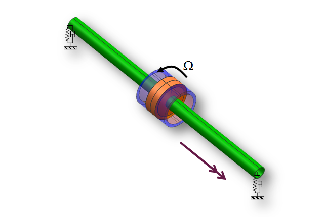
6.- Modeling Interconnected Coaxial Rotors
Beginning with NX Nastran 10, you can model interconnected coaxial rotors in a rotor dynamic analysis. Interconnected coaxial rotors are concentric rotors where one rotor is supported by the other. The support between the shafts is typically provided by a bearing.
An example of interconnected coaxial rotors are the high-pressure and low-pressure spools in some gas turbine configurations. The shafts for the two spools are separated by rolling element bearings. The inner race of the bearings rotate with the inner shaft, and the outer race of the bearings rotate with the outer shaft.
When you have interconnected coaxial rotors, one of the rotors is connected to a supporting structure or ground. The procedure to model this rotor is exactly the same as the procedure to model:
- An individual rotor that is connected to a supporting structure or ground.
- A non-interconnected coaxial rotor that is connected to a supporting
structure or
ground.
7.- Superelement-Style Reduction in Rotor Dynamics
Beginning with NX Nastran 10, you can improve the computational efficiency of a SOL 107 rotor dynamic solve by applying superelement-style reduction to the rotors. The implementation of superelement-style reduction in rotor dynamic analysis is distinctly different from the implementation of superelements in other types of analysis. For example, none of the NX Nastran user inputs for modeling superelements in other types of analysis is applicable to this new capability.
The procedure to use this new capability is as follows:
- Include a ROTSE bulk entry for each rotor you want to reduce. The presence of the ROTSE bulk entry in the input file triggers the superelement-style reduction capability in rotor dynamics. Match the value in the RSETID field of each ROTSE bulk entry with the corresponding RSETi field for the rotor on the ROTORD bulk entry. For each rotor that you define a ROTSE bulk entry, the software will automatically assign the grids on the corresponding ROTORG bulk entry to a unique o-set.
- On each ROTSE bulk entry, specify any grids that are listed on the corresponding ROTORG bulk entry that need to be removed from the o-set and placed in the a-set. Typically, these are the grids that connect the rotor to the supporting structure, or are the grids where loads like mass imbalance are applied.
- On each ROTSE bulk entry, specify whether the software should use real or complex modal reduction. Generally, you will want to select complex modal reduction.
Superelements …
1.- Unused q-set DOF.
In earlier versions of NX Nastran, the software removed all the unused q-set DOF in the definition of an external superelement. As a result, mechanism modes are calculated, but not retained in models with mechanisms.
Beginning with NX Nastran 10, you can use the QSETREM parameter to control whether or not the unused q-set DOF are removed when an external superelement is created with the EXTSEOUT case control command.
- If QSETREM = YES (default), unused q-set DOF are removed from the definition of the external superelement. Mechanism modes are calculated but not retained in models with mechanisms.
- If QSETREM = NO, all q-set DOF are retained in the definition of the external superelement. Mechanism modes are calculated and retained in models with mechanisms.
Specifying QSETREM = NO can lead to slow processing times for stresses, strains, and forces, especially if a large number of q-set DOF are defined but are not associated with calculated modes.

Multi-Step Nonlinear SOL401 …
1.- Introduction
The NX Nastran solution sequence, SOL 401 – NLSTEP, was first introduced in NX Nastran 9. It is a multistep, structural solution which supports a combination of linear or nonlinear static subcases and modal subcases.
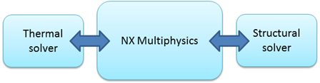
SOL 401 is the structural solution used by the NX Multiphysics environment within the NX Advanced Simulation product. The NX 10 Multiphysics environment now supports all combinations of structural-to-thermal and thermal-to-structural coupling with the NX Thermal solution. SOL 401 is also supported as a stand-alone NX Nastran solution.
2.- Enhancements Summary
The following is a summary of the SOL 401 enhancements in NX Nastran 10.
- New element types:
- The axisymmetric CQUADX4, CQUADX8, CTRAX3, CTRAX6 plane stress, plane strain and generalized plane strain elements are now supported.
- The plane stress CPLSTS3, CPLSTS4, CPLSTS6, CPLSTS8 elements are now supported.
- The plane strain CPLSTN3, CPLSTN4, CPLSTN6, CPLSTN8 and generalized plane strain (GPS) elements are now supported.
- The RBE2 and RBAR rigid elements are now supported with optional large displacement effects and thermal expansion.
- The RBE3 rigid element is also supported, but does not support the large displacement effects or thermal expansion.
- Contact:
- Surface-to-surface contact is now supported on the surfaces of 3D solid elements (CTETRA, CHEXA, CPENTA, CPYRAM). Edge-to-edge contact is now supported on the edges of plane stress/strain and axisymmetric elements. The contact condition can update when large displacement is turned on with PARAM,LGDISP,1.
- Glue:
- Edge-to-edge glue on the edges of plane stress/strain and axisymmetric elements is now supported, in addition to the already supported surface-to-surface glue. When large displacements are requested with PARAM,LGDISP,1, the glue stiffness orientation can update as a result of large displacement effects.
- Bolt preload:
- Bolt Preload is now supported. The bolt can be modeled with the 3D solid elements CHEXA, CPENTA, CTETRA, or with the 2D plane stress elements CPLSTS3, CPLSTS4, CPLSTS6, CPLSTS8.
- Plastic and creep materials:
- Plastic and creep materials can now be assigned to 3D solid elements, axisymmetric elements, plane stress elements, plane strain elements, and generalized plane strain elements. You can enable either plasticity or creep, or both, in all subcases, or in specific subcases.
- Temperature load enhancements:
- Time-assigned temperature loads are now supported. The ability to switch between time-assigned and time-unassigned temperature loads from one subcase to the next is also supported.
- The binary universal file (BUN) is the output format written from an NX Thermal analysis. The BUN file is now supported to optionally select time-assigned and time-unassigned temperatures stored in the external file.
- Mechanical load enhancements:
- Time-unassigned loads can now be selected with the LOAD case control command. Time-assigned and time-unassigned loads can be included in the same subcase.
- Time-assigned and time-unassigned enforced displacement loads that are defined using the SPCD bulk entry, are also supported.
- Modal subcase enhancements:
- Previously, the first subcase had to be of type STATIC. Now, a modal
subcase
can be the first subcase. - The case control setting SEQDEP=NO is now supported in a modal subcase
to
turn off all contributions from a previous static subcase. - A modal subcase which is not sequentially dependent (SEQDEP=NO) can
use
temperature dependent material properties that are defined using the MATTi
entries.
- Previously, the first subcase had to be of type STATIC. Now, a modal
subcase
- Force output enhancements:
- MPCFORCE and GPFORCE output requests are now supported. In general, MPCFORCE output can be requested with large displacements (PARAM,LGDISP,1). Although, it is computed based on the initial, undeformed configuration, GPFORCE output accounts for large displacements, except for DOF which are included in MPC equations.
- Crack simulation:
- You can now request the output of the j-integral for a given crack geometry. The j-integral output can be used by a third-party software like Zencrack to perform a fracture mechanics analysis. In addition, any face of a CHEXA element can now be collapsed to an edge. The edge of the collapsed face represents the crack front.
- Error estimator output for Adaptive Meshing:
- You can now request error estimates for certain types of elements when using SOL 401. The error estimates are computed and output on an individual element basis. Pre-processors like NX can use the error estimates to refine meshes.
Advanced NonLinear (SOL601/701) …
1.- New Potential-based Fluid Element.
A potential-based fluid element is available for SOL 601,106. The new element can be used in a static analysis where the pressure distribution in the fluid, and the displacement and stress distribution in the structure, is of interest. It has the following assumptions:
- Inviscid, irrotational medium with no heat transfer.
- Compressible or almost incompressible medium.
- Relatively small displacements of the fluid boundary.
The element material is defined using the existing MAT10 entry. It is supported by the 3D solid elements CHEXA, CTETRA, CPENTA, CPYRAM, the axisymmetric elements CQUADX4,CQUADX8, CTRAX3, CTRAX6, and the plane strain elements CPLSTN3, CPLSTN4, CPLSTN6, CPLSTN8. The axisymmetric and plane strain fluid elements must be defined on the XZ plane.
A fluid boundary is specified by referencing the BSURFS, BCPROPS, or BEDGE entries on the new BFLUID entry. The four types of fluid boundaries are fluid-fluid, fluid-structure, free surface, and rigid-wall. When the fluid elements are coupled with structural elements, the structural motions cause fluid pressure, and the fluid pressure causes additional forces to act on the structure.
2.- Strain-rate dependent Plastic Material
A strain-rate dependent plastic material is available in SOLs 601 and 701 to increase the yield stress with an increase in strain rate. The rate-dependent model applies to the isotropic plasticity models with isotropic hardening (bilinear or multilinear).
The new MATSR entry defines the strain-rate dependency, and has the same MID as the MATS1 entry. The MATSR entry is supported with the solid elements CHEXA, CTETRA, CPENTA, CPYRAM, the axisymmetric elements CQUADX4,CQUADX8, CTRAX3, CTRAX6, the plane stress elements CPLSTS3, CPLSTS4, CPLSTS6, CPLSTS8, the plane strain elements CPLSTN3, CPLSTN4, CPLSTN6, CPLSTN8, the shell elements CQUAD4, CQUAD8, CTRIA3, CTRIA6, CQUADR, CTRIAR, and the rod elements CROD, CONROD.
3.- New 3D Shell Element
A 2D shell element does not account for a change in thickness, and it assumes zero stress through the thickness. A 3D solid element does account for a change in thickness, but it locks when modeled as a thin shell.
A 3D shell element is now available for SOLs 601 and 701. In a large strain analysis, the 3D shell element accounts for the change in thickness, and the shift of the shell mid-surface from the halfway position.
The new 3D shell element is defined in 2D using the existing CQUAD4 or CTRIA3 entries, along with the new PSHL3D entry to define the element properties. The elastic (MAT1), plastic-cyclic (MATPLCY), and hyperelastic (MATHP, MATHE) materials are supported. Temperature dependent material properties defined with the MATTi entries are not supported.
4.- PCOMPG Entry Support
Shell composites defined with the PCOMP entry are supported in SOL 601. Now shell composities defined with the PCOMPG entry, which has global ply IDs, are also supported. The PCOMPG entry allows a global ply-numbering scheme across all composite definitions.
The inputs on the PCOMPG entry are the same as those on the PCOMP entry, except that each ply on the PCOMPG entry is assigned a global ID. The results output for a particular global ply ID will then apply to all composites in which you had included that ID.
5.- New Element Orientation
Previously, you could only define axisymmetric, plane stress and plane strain elements on the XZ plane for solutions 601 and 701. Now you can optionally define these elements on the XY plane for these solutions. Specifically, the axisymmetric elements CTRAX3, CQUADX4, CTRAX6, CQUADX8, the plane stress elements CPLSTS3, CPLSTS4, CPLSTS6, CPLSTS8, and the plane strain elements CPLSTN3, CPLSTN4, CPLSTN6, CPLSTN8 can be defined on either the XZ or XY plane of the basic coordinate system.
Additional information:
- The software automatically determines the orientation.
- All of these element types must be defined in a consistent plane.
- When axisymmetric elements are defined on the XZ plane, X is the radial direction, and Z is the axial direction. The grid points defining these elements must have X ≥ 0.0.
- When axisymmetric elements are defined on the XY plane, Y is the radial direction, and X is the axial direction. The grid points defining these elements must have Y ≥ 0.0.
- The new 2D potential fluid elements modeled as axisymmetric elements must be defined on the XZ plane.
6.- Bolt Preload Output
When a bolt preload is defined for SOL 601, the bolt loading is applied in special bolt loading iterations at the beginning of the analysis. Previously, results were not output for the bolt loading iterations. Beginning in NX Nastran 10, results will be output for the bolt loading iterations.
7.- Alternate Power Creep Input
SOL 601 supports the Exponential creep law and the Power creep law (also known as the Bailey-Norton creep model). The CREEP bulk entry can be used to define either of these creep laws. The Power creep law coefficients A, B, and D can also be defined as temperature dependent with the addition of the MATTC bulk entry.
Now the MATCRP bulk entry is available to alternately define the Power creep law. On the MATCRP entry, define the coefficients of the Bailey-Norton creep model in the A, B, and D fields.
- To define creep at a single temperature, enter real values.
- To define creep as temperature dependent, enter integer values that reference TABLEM1 entries.
Element Enhancements …
1.- Input/Output for 2-D Axisymmetric Elements
Before NX Nastran 10, the stiffness, mass, and loads for the CTRAX3, CQUADX4, CTRAX6, CQUADX8, CTRIAX, and CQUADX 2-D solid axisymmteric elements were based on a per radian section basis.
Now, the stiffness, mass, and loads for these elements are based on a 2*PI section basis. For example, to apply a distributed load of 135.0 Newton/mm on a single grid where the radius is 0.5 mm: The value entered on a FORCE entry = (Distributed force * 2 * π * Radius) = 135.0 N/mm * 2 * π * 0.5 mm = 424.115 Newtons.
The system cell 587 can optionally be set to 1 to revert to the per radian section basis. Note that the CTRAX3, CQUADX4, CTRAX6, CQUADX8, CTRIAX, and CQUADX elements are always on a per radian basis in solutions 601 and 701. In addition, the CTRAX3, CQUADX4, CTRAX6, and CQUADX8 elements are always on a 2*PI basis in a heat transfer solution.
In general, the section basis choice changes how force, strain energy, mass, volume, and work are computed. Displacement, pressure (surface tractions), stress, strain, and strain energy density will not change.
2.- CQUADR/CTRIAR Normal Rotational Stiffness
By default, the software computes stiffness in the normal rotational degree-of-freedom (R6) for the CQUADR and CTRIAR elements. The computed R6 stiffness improves the membrane accuracy. It is not computed for the other shell elements (CQUAD4, CQUAD8, CTRIA3, CTRIA6).
The new system cell 589 is available to control the CQUADR and CTRIAR element R6 stiffness.

GPU Computing …
The graphics processing unit (GPU) is used for many applications in which computations of large data can be done in parallel. A GPU is an add-on PCI Express card (PCIe) with its own onboard memory. The GPU approach to performance is to divide computations across a large number of relatively small cores. Some computationally intensive portions are offloaded to the GPU, while the remaining computations still run on the CPU.
GPU computing was first supported in NX Nastran 9.1 with the Linux system. Now in NX Nastran 10, it is supported on both Windows and Linux systems for the following cards and architectures.
- Intel’s MIC (Many Integrated Core) architecture, which is used by the Intel Xeon Phi, is supported for NX Nastran math computations. NX Nastran supports the Automatic Offload (AO) feature with the MIC-enabled MKL library. NX Nastran commonly calls MKL (math kernel libraries) in all solutions. When AO is enabled, and MKL library deems a computation as sufficiently large, it will automatically offload the computation to the MIC architecture.
- AMD GPU cards, and the NVIDIA GPU cards are supported for NX Nastran
matrix decomposition (DCMP module) and frequency response (FRRD1 module)
computations.
- Enabling GPU computations for the DCMP module will decrease the time for matrix decomposition. The impact will be more significant for sparse matrices reporting a maximum front size larger than 30K in the .f04 file.
- Enabling GPU computations for the FRRD1 module will speed up modal frequency response solutions (SOL 111) when viscous or structural damping produces coupled damping matrices. The impact becomes significant when the number of modes is at least 5,000.

Parallel Processing (DMP/SMP) …
1.- RDMODES improvements
Recursive Domain Normal Modes (RDMODES) is a parallel capability that uses substructuring technology for large scale normal modes analysis.
The RDMODES performance has improved in NX Nastran 10. The improvements reduce I/O and elapsed time. In one test case of a car body model that contains 384,000 elements, 391,000 grids, and 2,300,000 DOF, the elapsed time is reduced by 30% compared to NX Nastran 9.
RDMODES can run in either DMP, serial, or SMP configurations. No changes to the user interface are required to take advantage of the NX Nastran 10 improvements. The DMP, serial, and SMP runs will all benefit. You activate RDMODES by entering the Nastran keyword ‘nrec’ on the command line. To specify the desired parallel functionality, you can also enter the Nastran keywords ‘dmp’ or ‘smp’. Sample command line entries include:
- DMP: NASTRAN nrec = m dmp = p
- Serial: NASTRAN nrec = m
- SMP: NASTRAN nrec = m smp = p
where m is the number of external partitions and p is the number of processors.
Optimization Enhancements …
The optimizer choices for SOL200 are DOT (default) and Siemens DesignOptimization (SDO). You can select SDO by setting the system cell NASTRAN SYSTEM(425) = 1
- SDO enhancement:
- SDO has been enhanced to handle large optimization jobs that DOT may not be able to handle in terms of the number of constraints and number of design variables. The optimizer uses a linear programming approach coupled with an active constraint set algorithm and significant supporting code to expand and improve capabilities.
- SDO and DOT enhancements:
- The handling of beam dimensions related to internal constraints has been improved. The improvement prevents a violation of these constraints.
- The mode tracking process has been improved. Previously, if the process was unable to track a mode, it would end the solution with an error. Now, the software reports the mode tracking failure for the cycle to the .f06 file, and then continues with a smaller step size in an attempt to restore the mode tracking.
Miscellaneous …
1.- New keyword settings
The smemory and buffpool keywords now support the new optional input format nX, where n is a percentage and X is the total memory requested with the keyword memory. For example, if smemory=20.0X is defined, and 45Gb is requested with the keyword memory, the memory used for scratch memory is 20 percent of 45Gb, or 9Gb.
In addition, new memory keyword settings are included in the runtime configuration (RC) file. The file is included with the software installation at installation_directory\conf\nast10.rcf. The goal of these changes is to create a more efficient and robust out-of-the-box experience for a wider range of problems. If you open the RC file in a text editor, you will see the following new settings:
memory=.45*physical
smemory=20.0X
buffpool=20.0X
buffsize=32769
Note that the values in the RC file are not considered to be the default settings. The default settings are the values assigned internally by the program when the keywords are undefined.
2.- OP2 file default for the ILP-64 executable
The LP-64 executable always writes op2 files as 32-bit. However, the ILP-64 executable can optionally produce a 32-bit or a 64-bit op2 file. All integers and floating point data in a 64-bit op2 file have 64-bit precision.
- When you are using the ILP-64 executable, you can use the parameter OP2FMT to control if the op2 file is written as 32-bit or 64-bit:
- When PARAM,OP2FMT,32, the software writes the op2 file as 32-bit.
- When PARAM,OP2FMT,64, the software writes the op2 file as 64-bit.
- When PARAM,OP2FMT,0, the software automatically checks if a PARAM,POST,n entry exists. If n is less than 0, the OP2 file is written as 32-bit. If not, the OP2 file is written as 64-bit.
In NX Nastran 9 and 9.1, the default was PARAM,OP2FMT,0. The new default for NX Nastran 10 is PARAM,OP2FMT,32.
In addition, now in NX Nastran 10 when you are using the ILP-64 executable and SYSTEM(525)=1 is defined, the OP2FMT parameter is ignored, and the software will write the op2 file as 64-bit. The maximum integer in this scenario is 11 digits, or 99,999,999,999. A fatal error will occur if an integer exceeds this limit.
NX Nastran 10.0 Supported Platforms
Hardware Executable Type Supported OS 1st Supported Rel.
 -------- --------------- ------------ ------------------

 Intel x86-64 LP-64* SuSE ES 10.0 8.0
 Intel x86-64 LP-64* DMP* SuSE ES 10.0 8.0
 Intel x86-64 LP-64* SuSE ES 11.0 7.1
 Intel x86-64 LP-64* DMP* SuSE ES 11.0 7.1
 Intel x86-64 LP-64* SuSE ES 11.0 SP4 10.0
 Intel x86-64 LP-64* DMP* SuSE ES 11.0 SP4 10.0
 Intel x86-64 LP-64* Redhat EL 5.0 5.1
 Intel x86-64 LP-64 DMP* Redhat EL 5.0 5.1
 Intel x86-64 LP-64* Redhat EL 6.0 8.0
 Intel x86-64 LP-64 DMP* Redhat EL 6.0 8.0
 Intel x86-64 LP-64* Redhat EL 7.0 10.0
 Intel x86-64 LP-64 DMP* Redhat EL 7.0 10.0
 Intel x86-64 LP-64* CentOS 6.0 10.0
 Intel x86-64 LP-64 DMP* CentOS 6.0 10.0
 Intel x86-64 LP-64* CentOS 7.0 10.0
 Intel x86-64 LP-64 DMP* CentOS 7.0 10.0

 Intel x86-64 ILP-64* SuSE ES 10.0 8.0
 Intel x86-64 ILP-64* DMP* SuSE ES 10.0 8.0
 Intel x86-64 ILP-64* SuSE ES 11.0 7.1
 Intel x86-64 ILP-64* DMP* SuSE ES 11.0 7.1
 Intel x86-64 ILP-64* SuSE ES 11.0 SP4 10.0
 Intel x86-64 ILP-64* DMP* SuSE ES 11.0 SP4 10.0
 Intel x86-64 ILP-64* Redhat EL 5.0 5.1
 Intel x86-64 ILP-64 DMP* Redhat EL 5.0 5.1
 Intel x86-64 ILP-64* Redhat EL 6.0 8.0
 Intel x86-64 ILP-64 DMP* Redhat EL 6.0 8.0
 Intel x86-64 ILP-64* Redhat EL 7.0 10.0
 Intel x86-64 ILP-64 DMP* Redhat EL 7.0 10.0
 Intel x86-64 ILP-64* CentOS 6.0 10.0
 Intel x86-64 ILP-64 DMP* CentOS 6.0 10.0
 Intel x86-64 ILP-64* CentOS 7.0 10.0
 Intel x86-64 ILP-64 DMP* CentOS 7.0 10.0

 Intel x86-64 IP-64* Windows Server 2008 R2 8.0
 Intel x86-64 LP-64 DMP* Windows Server 2008 R2 8.0
 Intel x86-64 IP-64* Windows Server 2012 R2 10.0
 Intel x86-64 LP-64 DMP* Windows Server 2012 R2 10.0
 Intel x86-64 LP-64* Windows 7 SP1** 8.0
 Intel x86-64 LP-64* Windows 8.1 9.0

 Intel x86-64 IIP-64* Windows Server 2008 R2 8.0
 Intel x86-64 ILP-64 DMP* Windows Server 2008 R2 8.0
 Intel x86-64 IIP-64* Windows Server 2012 R2 10.0
 Intel x86-64 ILP-64 DMP* Windows Server 2012 R2 10.0
 Intel x86-64 ILP-64* Windows 7 SP1** 8.0
 Intel x86-64 ILP-64* Windows 8.1 9.0
NOTES:
- With this release NX Nastran is no longer being released for either the 32-bit Windows platform nor for the AIX platform.
- As communicated previously NX NASTRAN 7.0 ends the support of the HP-UX (PA-RISC), Sun Solaris, and 32-bit Linux platforms.
- Support for SGI IRIX was discontinued with the NX NASTRAN 6.0 release *X86-64 refers to the the various 64bit Intel chips including, but not limited to, the 64bit Pentium D, the Core 2 Duo, Core 2 Quad, and the 64bit Xeon series of processors.
- ***Supported versions of Microsoft Windows 7 are limited to Windows 7 Pro and Windows 7 Enterprise. All testing was performed using Windows 7 Enterprise.
Saludos,
Blas.
- NOTA:
La futura nueva versión de FEMAP V11.2 traerá ya incluido en el DVD de instalación la nueva versión de NX NASTRAN V10.0
")
SÍGUENOS
EN: ![]()
![]()
![]()
![]()